Provisioning
Recommended Approach
You can also provision and perform lifecycle management of GKE clusters using the Template Catalog. This is the recommended approach.
Cloud Credentials
The controller needs to be configured with GKE Credentials in order to programmatically create and configure required GCP infrastructure. These credentials securely managed as part of a cloud credential in the Controller.
The creation of a cloud credential is a "One Time" task. It can then be used to create clusters in the future when required. Refer GKE Credentials for additional instructions on how to configure this.
Important
To guarantee complete isolation across Projects (e.g. BUs, teams, environments etc.,), cloud credentials are associated with a specific project. These can be shared with other projects if necessary.
Prerequisites
Users must have the below setup in the GCP Console
-
Create Service Account with the below Roles:
- Compute Admin
- Kubernetes Engine Admin
- Service Account User
-
APIs on Google Cloud Platform
Enable the following APIs on your Google Cloud platform to provision a GKE cluster
- Cloud Resource Manager API: Used for validating user’s GCP project
- Compute Engine API: Used for validating and accessing various resources like zones, regions etc,. on GCP that are used by the GKE cluster
- Kubernetes Engine API
-
Cluster in a VPC network
- Ensure the firewall allows HTTP and HTTPs traffic
- Create the subnet that you want to use before you create the cluster
- GCP VPC is global but subnet should be in the same region as your target cluster
High Level Steps
The image below describes the high level steps to provision and manage GKE clusters using the controller.
sequenceDiagram
    autonumber
    participant user as User/Pipeline
    participant rafay as Controller
    participant boot as Bootstrap Node
    participant gke as GKE Cluster
    user->>rafay: Provision GKE Cluster (UI, CLI)
    note over boot, gke: GCP Project
    rect rgb(191, 223, 255)
    note right of rafay: For Every New GKE Cluster
    rafay->>boot: Provision Bootstrap VM in GCP Project
    rafay->>boot: Apply GKE cluster spec
    boot->>gke: Provision GKE Cluster
    boot->>gke: Pivot CAPI mgmt resources
    boot->>gke: Apply Cluster Blueprint
    gke->>rafay: Establish Control Channel with Controller
    rafay->>boot: Deprovision Bootstrap Node
    gke->>rafay: GKE Cluster Ready
    end
    rafay->>user: GKE Cluster Provisioned
Self Service UI
The controller provides users with a "UI Wizard" type experience to configure, provision and manage GKE clusters. The wizard prompts the user to provide critical cluster configuration details organized into logical sections:
- General
- Network Settings
- NodePools
- Security
- Feature
- Advanced
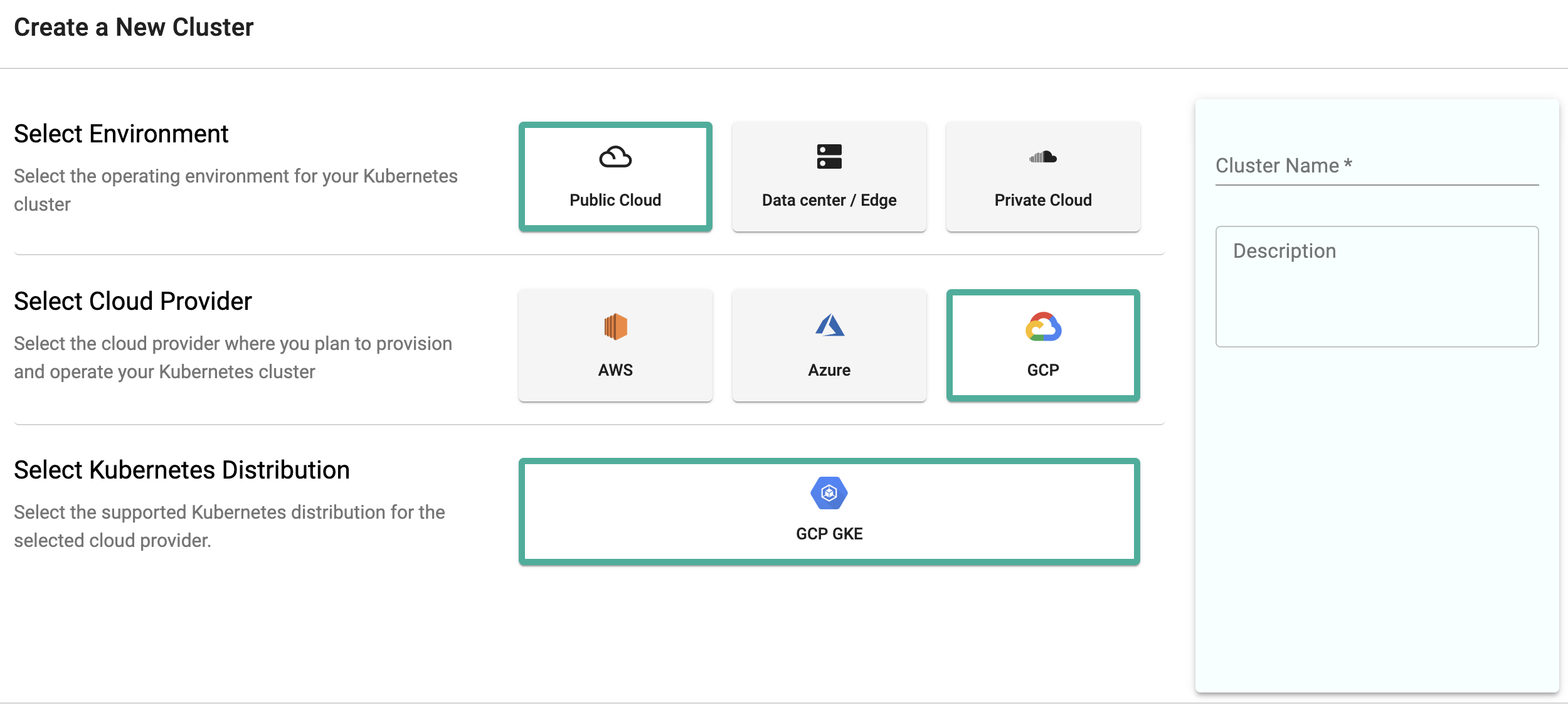
Create Cluster
- Click Clusters on the left panel and the Clusters page appears
- Click New Cluster
- Select Create a New Cluster and click Continue
- Select the Environment Public Cloud
- Select the Cloud Provider GCP and Kubernetes Distribution GCP GKE
- Provide a cluster name and click Continue
Constraints
- a. The cluster name should not exceed 40 characters
- b. Always begin with a letter. The name cannot start with a number or any other character
- c. The cluster name should not end with a hyphen ("-")
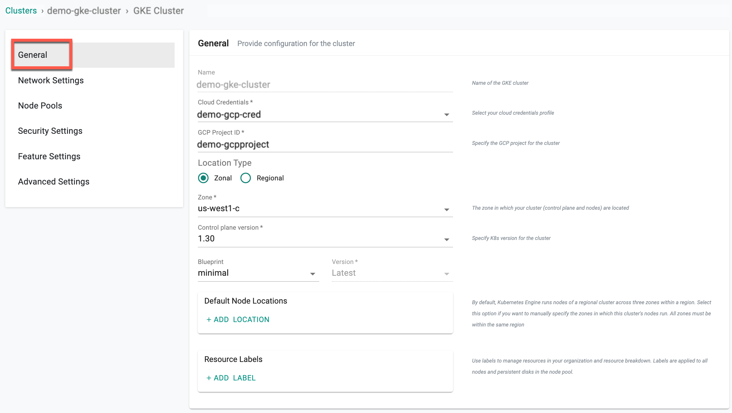
General (Mandatory)
General section is mandatory to create a cluster
- Select the Cloud Credential from the drop-down created with GCP credentials
- Enter the required GCP Project ID name
- Select a Location Type, either Zonal or Regional
- On selecting Zonal, select a zone
- On selection Regional, select a Region and Zone
- Select a Control plane version
- Select a Blueprint Type and version
- Specify the Default Node Locations to define the zone(s) where the cluster’s nodes run
- Add Resource Labels to assign cluster-level tags for tracking, and automation
Important
Use the GCP Project ID and not the Project Name.
📘 Note: "Resource Label Support"
Supported Features
- Day 0 and Day 2 support for cluster resource labels (across all interfaces).
- Day 0 support for nodepool labels (across all interfaces).
Current Limitations
- If a cluster already has out-of-band cluster labels, they will be reconciled by the new changes.
To retain these labels, copy the existing labels and include them in the Rafay cluster spec.
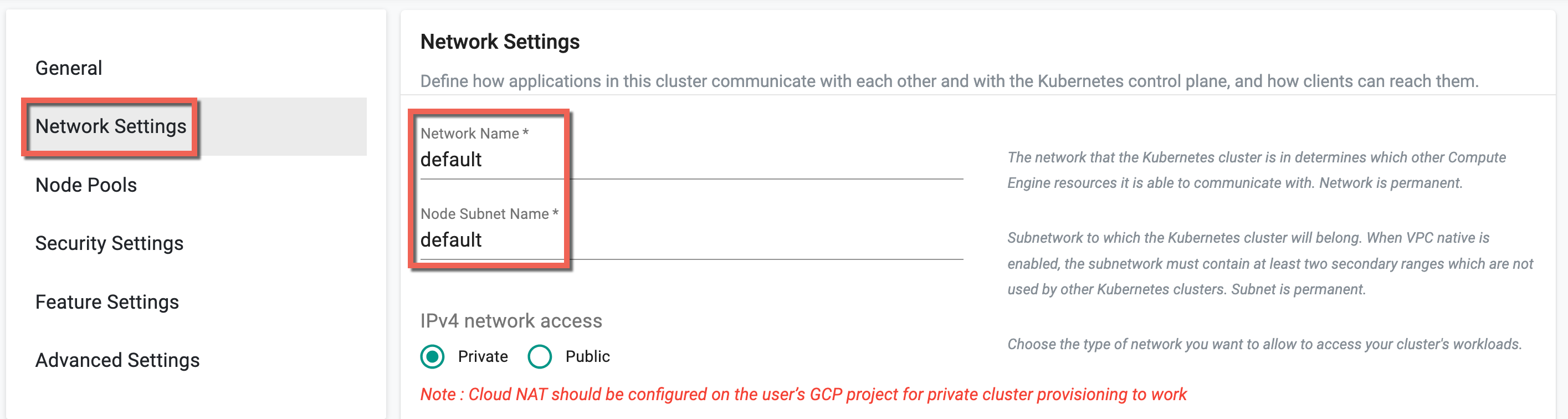
Network (Mandatory)
This section allows to customize the network settings
- Provide a Network Name and Node Subnet.
| Field Name | Field Description |
|---|---|
| Network Name | The name of the Google Cloud network that the cluster will be created in. |
| Node Subnet Name | The name of the subnet in the network that the nodes in the cluster will be created in. |
Note: Use the name for the network and node subnet. Do not use the CIDR.
If using the VPC Network of the same project, the values are set to default.
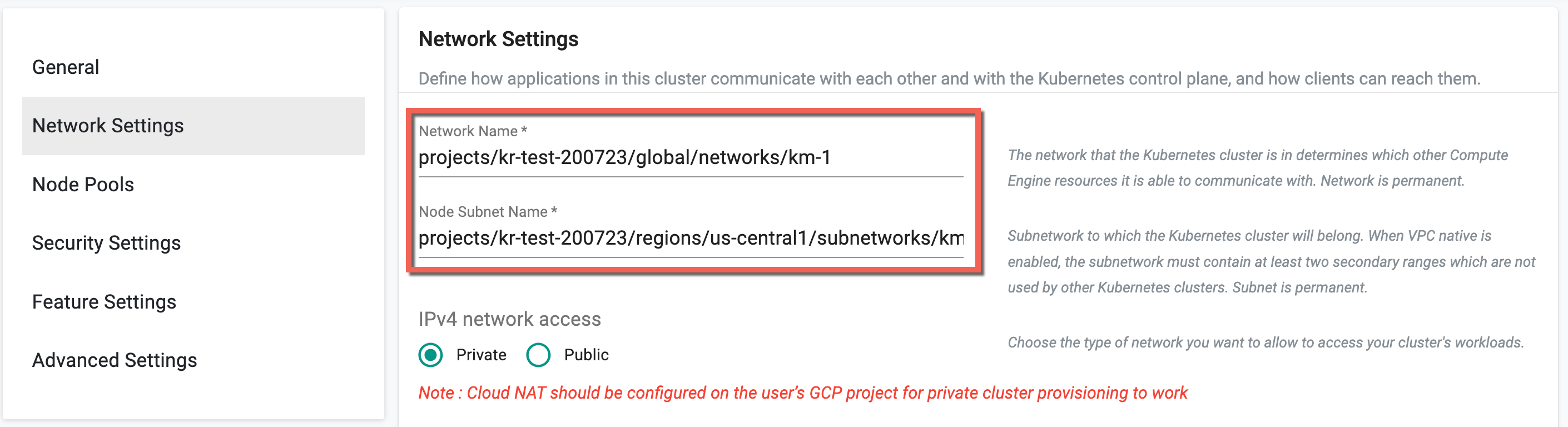
To utilize the shared VPC Network (shared by host projects via GKE Console), provide the shared network paths for Network Name and Node Subnet Name as illustrated below.
| Field Name | Field Description |
|---|---|
| IPv4 network access | Choose the type of network to allow access to your cluster's workloads. Learn more about public and private clusters in Google Kubernetes Engine. |
| Public Cluster | Choose a public cluster to allow access from public networks to the cluster's workloads. Routes aren't created automatically. This setting is permanent and cannot be changed after the cluster is created. Learn more about public and private clusters in Google Kubernetes Engine |
| Private Cluster | Choose a private cluster to assign internal IP addresses to Pods and nodes, isolating the cluster's workloads from public networks. This setting is permanent and cannot be changed after the cluster is created. Learn more about public and private clusters in Google Kubernetes Engine |
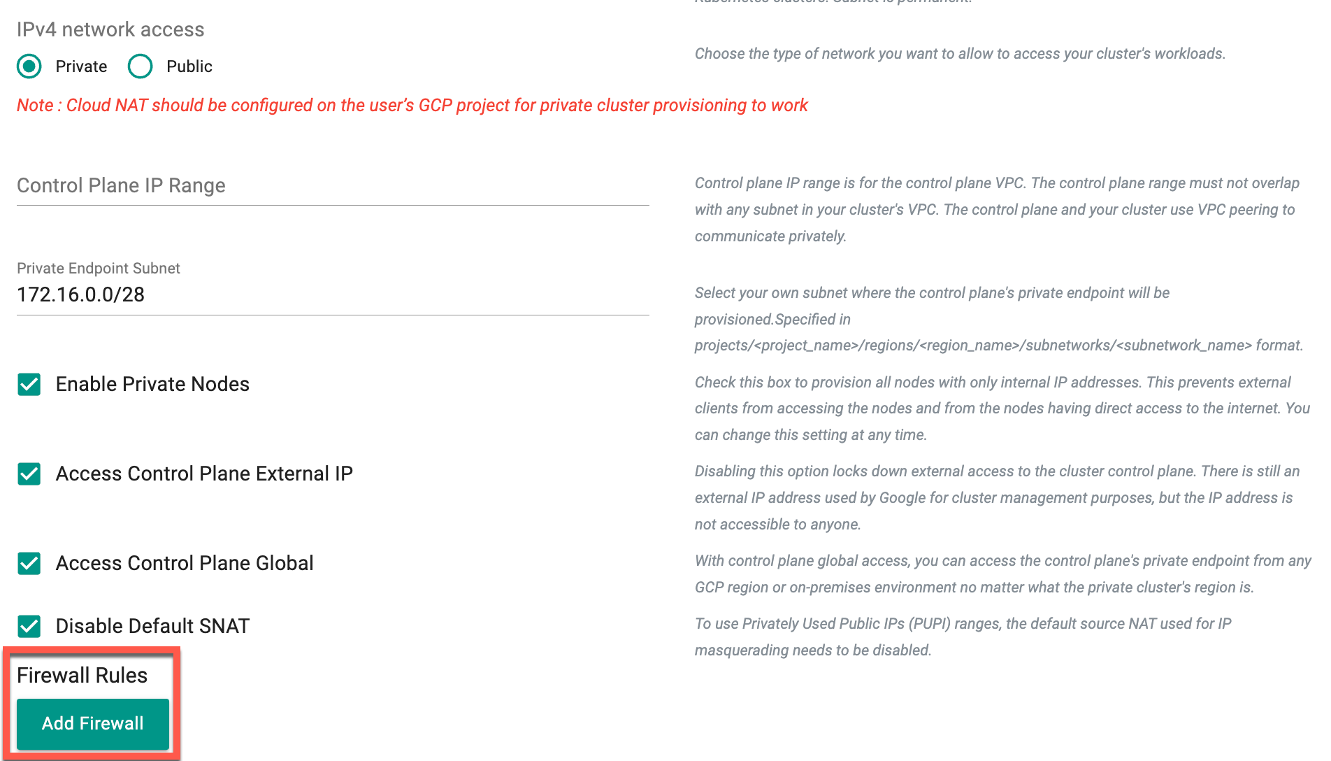
| Control Plane IP Range | The control plane IP range is associated with the control plane VPC. Ensure that the control plane range does not overlap with any subnet in your cluster's VPC. The control plane and the cluster communicate privately using VPC peering |
| Enable Private Nodes | Check this option to provision all nodes with only internal IP addresses. Enabling this prevents external clients from accessing the nodes and blocks nodes from having direct access to the internet. This setting can be modified at any time |
| Access control plane using its external IP address | Disabling this option locks down external access to the cluster control plane. Google still uses an external IP address for cluster management purposes, but it's not accessible to anyone. This setting is permanent |
| Enable Control plane global access | With control plane global access, access the control plane's private endpoint from any GCP region or on-premises environment, regardless of the cluster's region. Learn more |
| Disable Default SNAT | To use Privately Used Public IPs (PUPI) ranges, disable the default source NAT used for IP masquerading. Learn more |
| Cluster default Pod address range | Define the IP address range for all pods in the cluster. Use CIDR notation, leave blank for the default range. This setting is permanent |
| Maximum Pods per node | Determine the size of IP address ranges assigned to nodes on GKE. Pods on a node are allocated IP addresses from its assigned CIDR range. Optimize the partitioning of the cluster's IP address range at the node level. This setting is permanent. Learn more |
| Service address range | Define the IP address range for Kubernetes services in the cluster's VPC network. Use CIDR notation, leave blank for the default range. This setting is permanent |
| Pod Secondary CIDR Range (Name) | Provide the Pod name reserved in the VPC network. Mandatory if shared VPC Network used |
| Service Secondary CIDR Range (Name) | Provide the Service name reserved in the VPC network. Mandatory if shared VPC Network used |
- Select a Cluster Privacy, Private or Public and provide the relevant details
🛑 Important:
When choosing the "Private" cluster privacy option, it is required to have at least one (1) Cloud NAT present in the project where the GKE cluster is being created.
The Enable Private Nodes flag is optional. When enabled, it instructs GKE to create the cluster with private nodes, ensuring the nodes do not have external IP addresses.
The Private Endpoint Subnet flag defines the IP address range of the control plane's internal endpoint.
The Control Plane IP Range flag can be used as an alternative to the Private Endpoint Subnet flag. When used, it provisions the internal IP address for the control plane.
Choosing the Appropriate Flag: - If the Enable Private Nodes flag is used, both Control Plane IP Range and Private Endpoint Subnet flags are optional.
- If the Private Endpoint Subnet flag is specified, GKE provisions the control plane’s internal endpoint with an IP address from the range defined in the flag.
- If the Control Plane IP Range flag is provided, GKE creates a new subnet with the given range and provisions the control plane's internal endpoint with an IP from this new subnet.
- If both Private Endpoint Subnet and Control Plane IP Range flags are omitted, GKE will provision the control plane internal endpoint with an IP from the secondary cluster's subnetwork.
Important
-
Optionally, users can Add Firewall Rules.
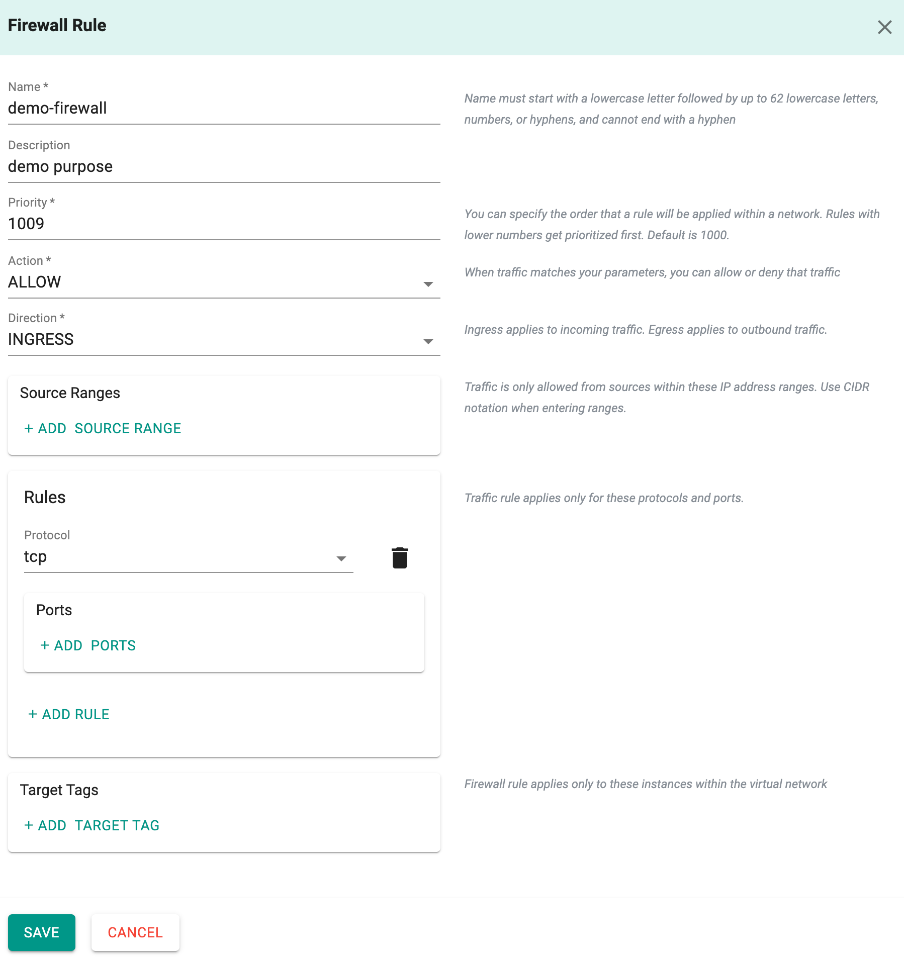
Firewall Rules
Adding Firewall Rules for GKE Private Cluster allows users to create and manage firewall rules tailored to their specific needs. This capability enhances network security by providing granular control over inbound and outbound traffic within GKE private clusters. Users can define custom firewall policies, ensuring only authorized connections are permitted while blocking unauthorized access attempts. This feature empowers users with greater control and flexibility in managing network traffic within GKE private cluster environments.
- Click Add Firewall and Firewall Rule page appears
- Provide a name and the required details
Field Name Field Description Name* Specifies a name for the Firewall rule Description Provides an optional description for this resource. Include this field during resource creation Priority* Determines the priority of this rule. It accepts integers between 0 and 65535, inclusively, with a default value of 1000. Relative priorities govern which rule takes precedence in case of conflicts Action* Defines the action taken when traffic matches specified parameters: ALLOW or DENY Direction* Indicates the traffic direction to which this firewall applies: INGRESS or EGRESS. The default is INGRESS. For EGRESS traffic, sourceTags fields cannot be specified Source Ranges Specifies source IP ranges for which the firewall rule applies. Ranges must be in CIDR format and apply only to IPv4 traffic Destination Ranges If destination ranges are specified, the firewall rule applies exclusively to traffic with destination IP addresses within these ranges, which must be expressed in CIDR format. Only IPv4 is supported Rules* Lists rules defined by this firewall. Each rule describes a permitted connection using a protocol and port-range tuple Ports: Optional list of ports to which this rule applies, relevant only for UDP or TCP protocol. Each entry must be an integer or a range. If unspecified, the rule applies to connections through any port. Example inputs include: ["22"], ["80","443"], and ["12345-12349"] Protocol: Specifies the IP protocol to which this rule applies. The protocol type is mandatory when creating a firewall rule and can be a well-known protocol string (tcp, udp, icmp, esp, ah, ipip, sctp) or the IP protocol number Target Tags Enumerates tags controlling which instances the firewall rule applies to. If specified, the rule applies exclusively to instances in the VPC network tagged accordingly Note: Depending on the chosen Direction (Ingress or Egress), users are required to add either Source Ranges or Destination Ranges. If Ingress is selected, Source Ranges must be added, while for Egress, Destination Ranges are necessary. Adding either Source Ranges or Destination Ranges is mandatory, but not both simultaneously.
- Click Save
-
Optionally, enter the Pod Address Range and Service Address Range
- If not providing any value for Pod Address Range, each node in GKE receives a /24 alias IP range of 256 addresses for hosting the Pods that run on it
- If not providing any value for Service Address Range, service (cluster IP) addresses are taken from the cluster's subnet's secondary IP address range for Services. This range must be large enough to provide an address for all the Kubernetes Services you host in your cluster
-
Enter the count for Max Pods Per Node

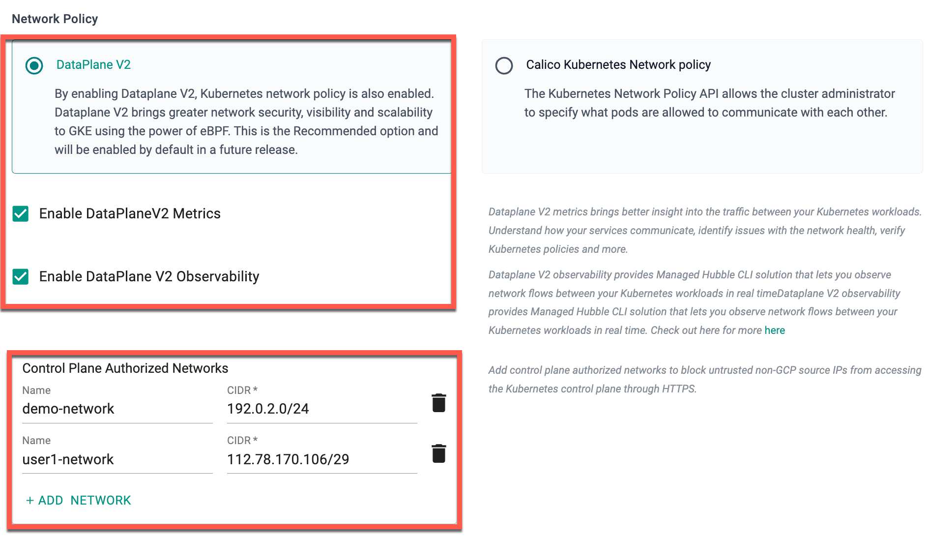
Dataplane V2 and Network Policy Config
-
Enabling DataPlane V2 in GKE activates Kubernetes network policy and enhances network security, visibility, and scalability using eBPF technology. This option is recommended for optimal performance and is particularly beneficial for large-scale applications. If DataPlane V2 is enabled, users are allowed to enable DataPlaneV2 Metrics and DataPlane V2 Observability
- Enabling DataPlane V2 metrics allows the users to optimize network performance, troubleshoot connectivity issues, and ensure the overall reliability of your Kubernetes environment with greater ease.
- Enabling DataPlane V2 Observability provides a Managed Hubble CLI solution for real-time observation of network flows between Kubernetes workloads. This feature offers valuable insights into communication patterns, facilitating efficient monitoring and troubleshooting to ensure network reliability and security.
Refer to this page to learn about the limitations of GKE DataPlane V2.
-
Enabling the Calico Kubernetes Network Policy option in GKE clusters enhances security, visibility, and scalability by activating the Network Policy API. With fine-grained control and efficient eBPF technology, it ensures robust security and high performance for large-scale deployments, simplifying network policy management for secure microservices and multi-tenancy environments.
Refer to this page to learn about the limitations of GKE Network Policy.
Important
Users are allowed to enable either DataPlane V2 or Calico Kubernetes Network Policy during GKE cluster creation, but not both simultaneously.
- If Private Cluster is selected, there are two options: setting the Access Control Plane External IP or configuring an Authorized Network. In the former, only a specific external IP assigned by Google can access the cluster, while in the latter, a CIDR range is provided, permitting all IPs within that range to access the private cluster
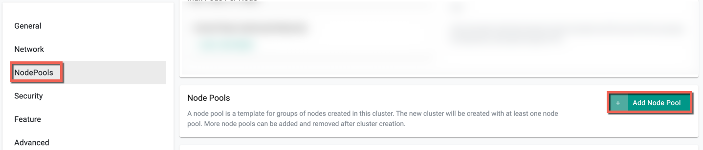
NodePools
By default, a new cluster will be created with at least one node pool
- To add more node pools, click Add Node Pool
- Enter a name and select the required Node K8s version
- Enter the number of nodes
- Enable/disable Node Zone. On enabling, add one or more zone(s)
- Enable/disable cluster autoscaler to automatically create or delete nodes based on the workload
- Enable/disable Automatically upgrade nodes to the next available version. Enabling this option will automatically upgrade the nodes within a cluster to the latest available version. Ensure that the Node K8s version matches the control plane version exactly or is within one minor version lower when auto upgrade nodes version is enabled
- To implement a node pool upgrade strategy, activate the Configure Upgrade Settings. Enabling this option will display two strategies to choose from. Opt for either the Surge Upgrade or the Blue Green Upgrade based on the requirement
Surge Upgrade
On selecting surge upgrade, nodes are upgraded one by one or in small batches with controlled disruption. This type of strategy for upgrading node pools includes two (2) important settings: - Max Surge: This determines how many new nodes can be added at most to the node pool while upgrading. It ensures a controlled and gradual increase in capacity. - Max Unavailable: This sets the maximum number of nodes that can be offline simultaneously (not in Ready state) during the upgrade. It's about managing node downtime carefully to prevent service disruptions.
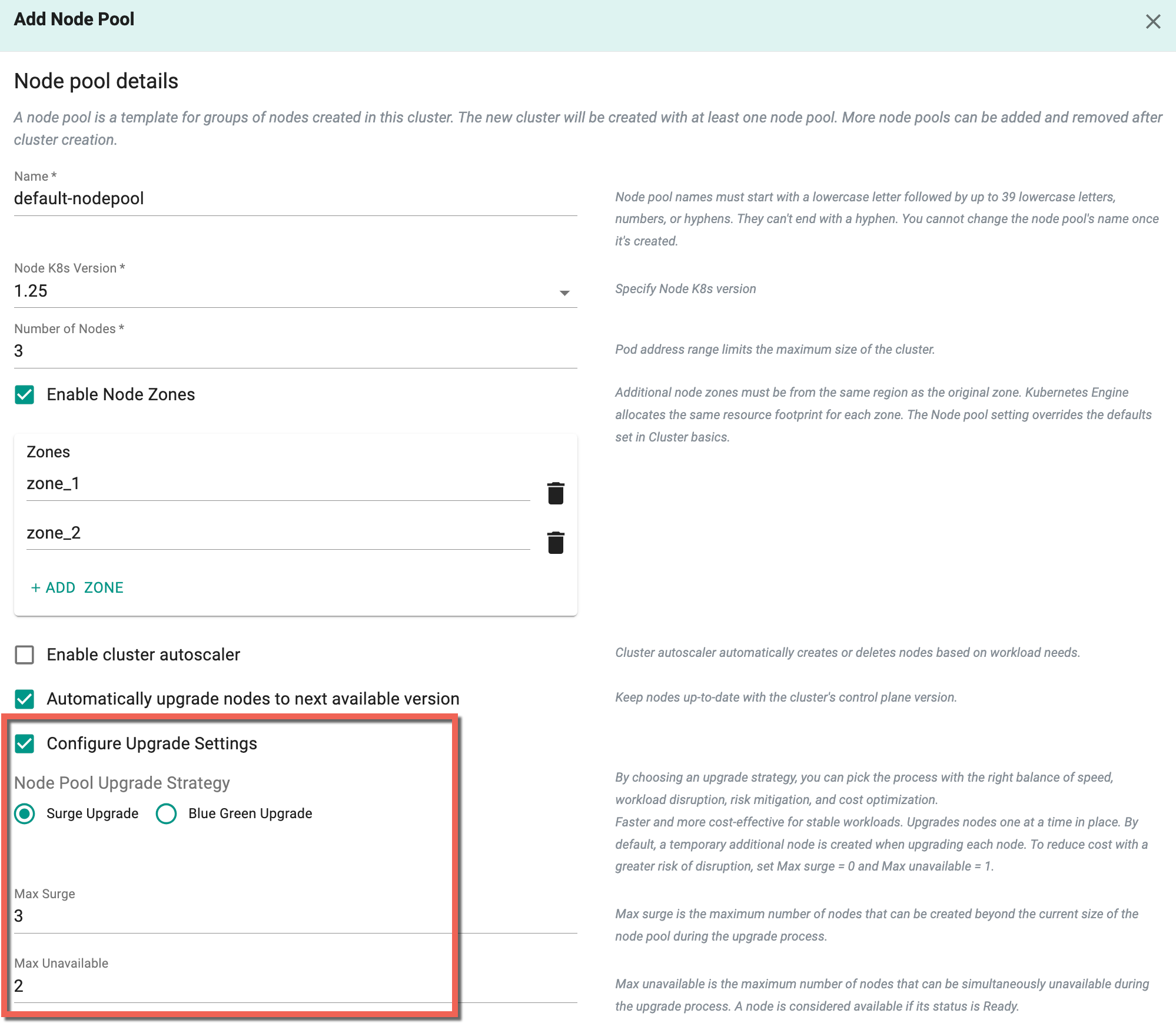
Important
- Sum of Max Surge and Max Unavailable should not exceed 20
- Max Surge value cannot be zero '0' if Max Unavailable is set to zero '0'
Blue Green Upgrade
On selecting Blue Green Upgrade, a new set of nodes with updates is created, validated, and can be switched to while keeping the old nodes as a backup, allowing for easy rollback if needed. This type of strategy for upgrading node pools includes three(3) specific pieces of information:
-
Batch Node Count: This is the fixed number of nodes to be gradually drained in each batch. If this number is set to zero, this step will be skipped entirely.
-
Batch Soak Duration: This indicates the amount of time, measured in seconds, to pause after every batch of nodes has been drained. During this pause, you can assess your workload to make sure everything is functioning as expected after the nodes have been upgraded.
-
Nodepool Soak Duration: After all batches have been completely drained, this duration in seconds is the waiting time before proceeding. It provides an opportunity for you to double-check your workload's health before proceeding further.
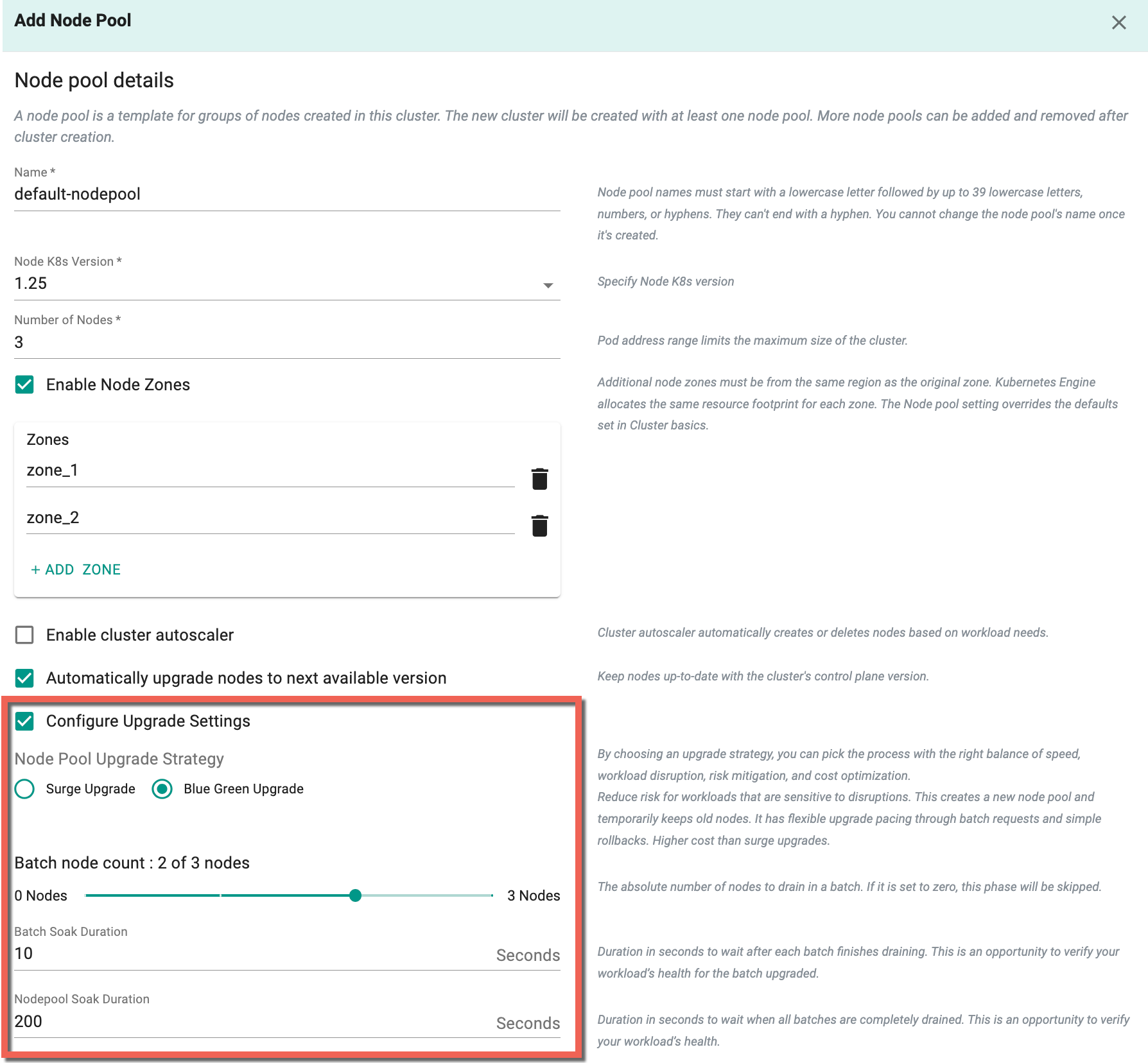
Important
The max duration for Batch Soak Duration is 604800 seconds
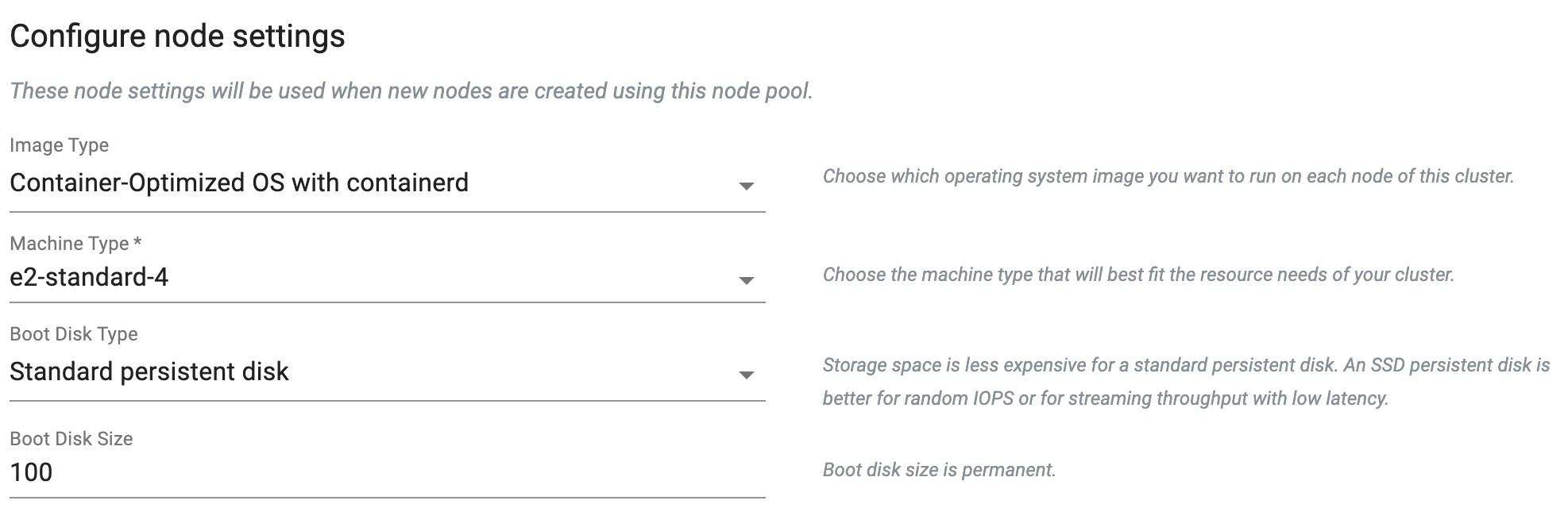
- Optionally, provide the details for Configure Node settings, GPU Settings, and Reservation Affinity details
Configure node settings
Configure node settings ensures that any new nodes created within this node pool will adhere to the specified configurations
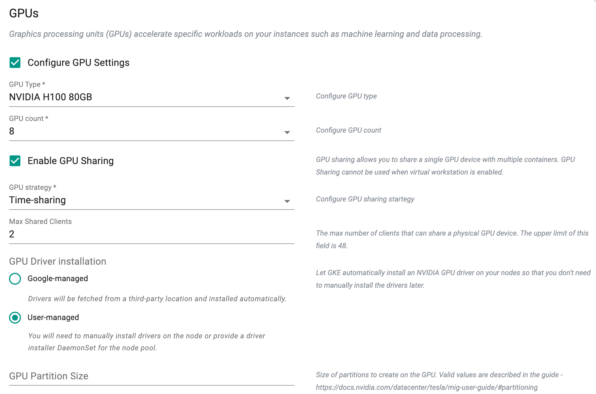
GPU Configuration
Optionally, enable Configure GPU Settings and provide the required details
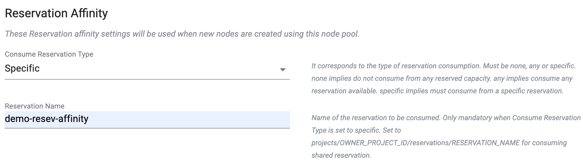
Reservation Affinity
Provide the required Reservation Affinity settings config details
- Optionally, provide Node networking, Node security, and Node metadata
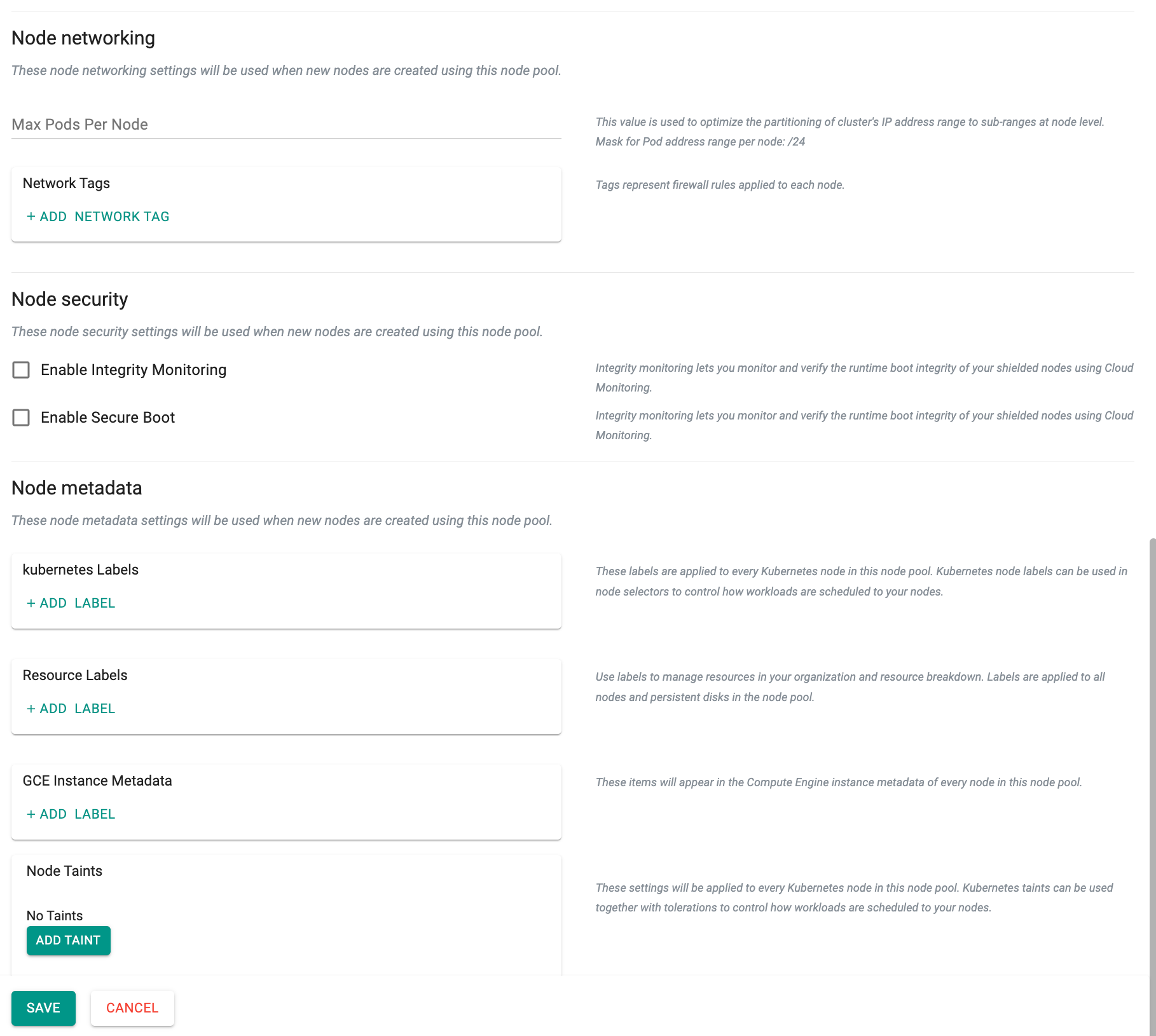
- Click Save
Security (Optional)
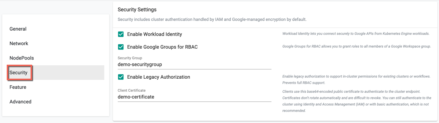
This section allows to customize the Security Settings
- Enable Enable Workload Identity to connect securely to Google APIs from Kubernetes Engine workloads
- Enable Enable Google Groups for RBAC to grant roles to all members of a Google Workspace group. On enabling this option, enter the required group name
- Enable Enable Legacy Authorization to support in-cluster permissions for existing clusters or workflows and this prevents full RBAC support
- Provide Client Certificate to authenticate to the cluster endpoint
| Field Name | Field Description |
|---|---|
| Workload Identity | Workload Identity is a feature of Google Kubernetes Engine (GKE) that allows workloads running on GKE to securely access Google Cloud services. It enables you to assign distinct, fine-grained identities and authorization for each application in your cluster. |
| Google Groups for RBAC | Google Groups for RBAC lets you assign RBAC permissions to members of Google Groups in Google Workspace. Learn more |
| Legacy Authorization | Legacy Authorization enables in-cluster permissions for existing clusters or workflows. It does not support full RBAC. Learn more |
| Issue a client certificate | The "Issue a Client Certificate" setting controls whether a client certificate will be issued for the cluster. Client certificates provide an additional layer of security when authenticating to the cluster endpoint (Kubernetes API server). Note that certificates don't rotate automatically and revoking them can be difficult. You can still authenticate to the cluster using Identity and Access Management (IAM) or basic authentication, although it is not recommended. |
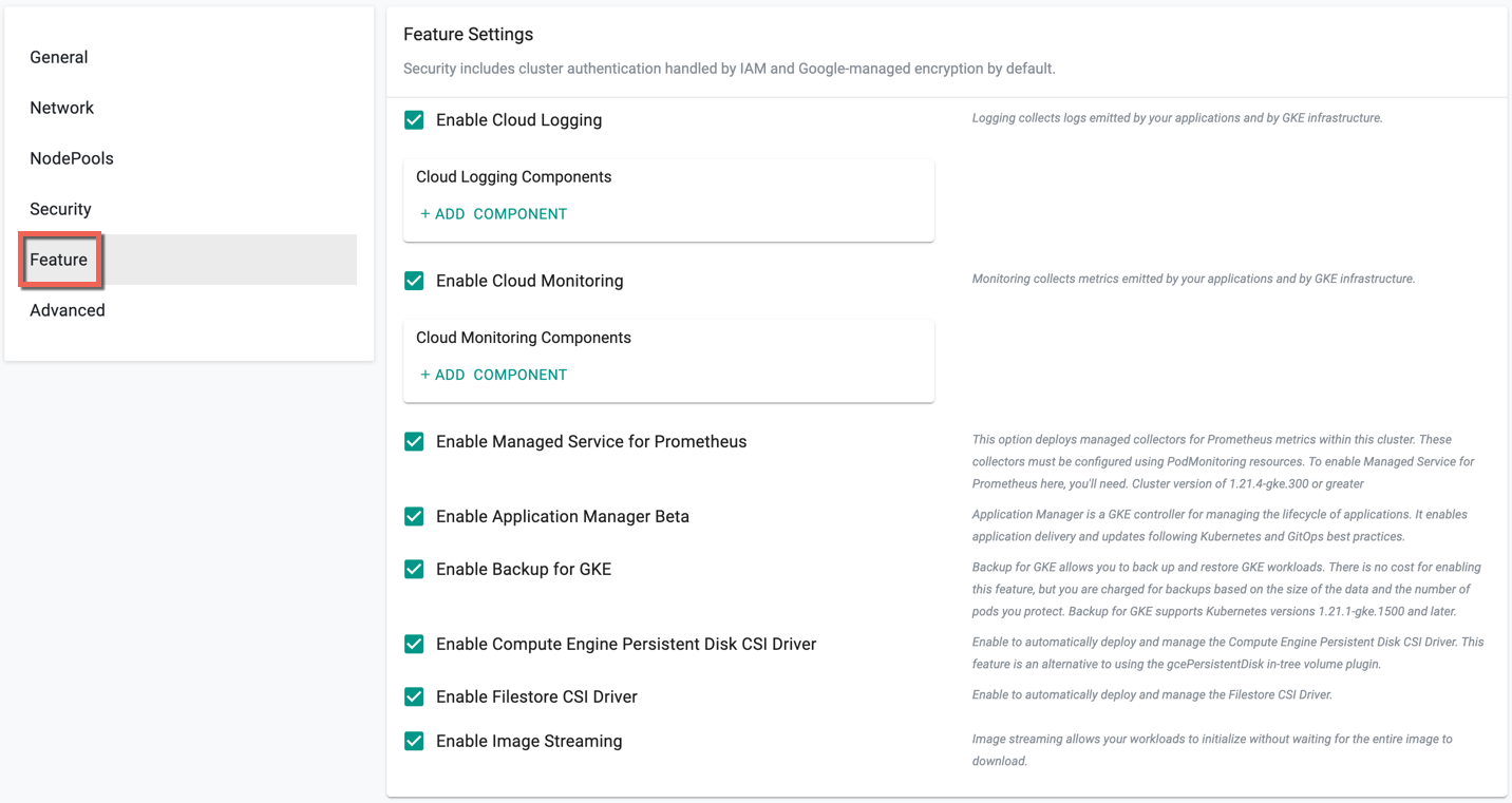
Feature Setting (Optional)
Enable the required features
| Field Name | Field Description |
|---|---|
| Cloud Logging | Collect logs emitted by your applications and GKE infrastructure. Learn more |
| Enable Cloud Monitoring | Monitor metrics emitted by your applications and GKE infrastructure. Learn more |
| Enable Managed Service for Prometheus | Deploy managed collectors for Prometheus metrics within this cluster. These collectors must be configured using PodMonitoring resources. Learn more |
| Enable Backup for GKE | Enable backup and restore for GKE workloads. Costs are based on the data size and the number of protected pods. Learn more |
| Enable Filestore CSI Driver | Automatically deploy and manage the Filestore CSI Driver in this cluster. Learn more |
| Enable Image Streaming | Allow workloads to initialize without waiting for the entire image to download. Learn more |
| Enable Compute Engine Persistent Disk CSI Driver | Automatically deploy and manage the Compute Engine Persistent Disk CSI Driver. This feature is an alternative to using the gcePersistentDisk in-tree volume plugin. Learn more |
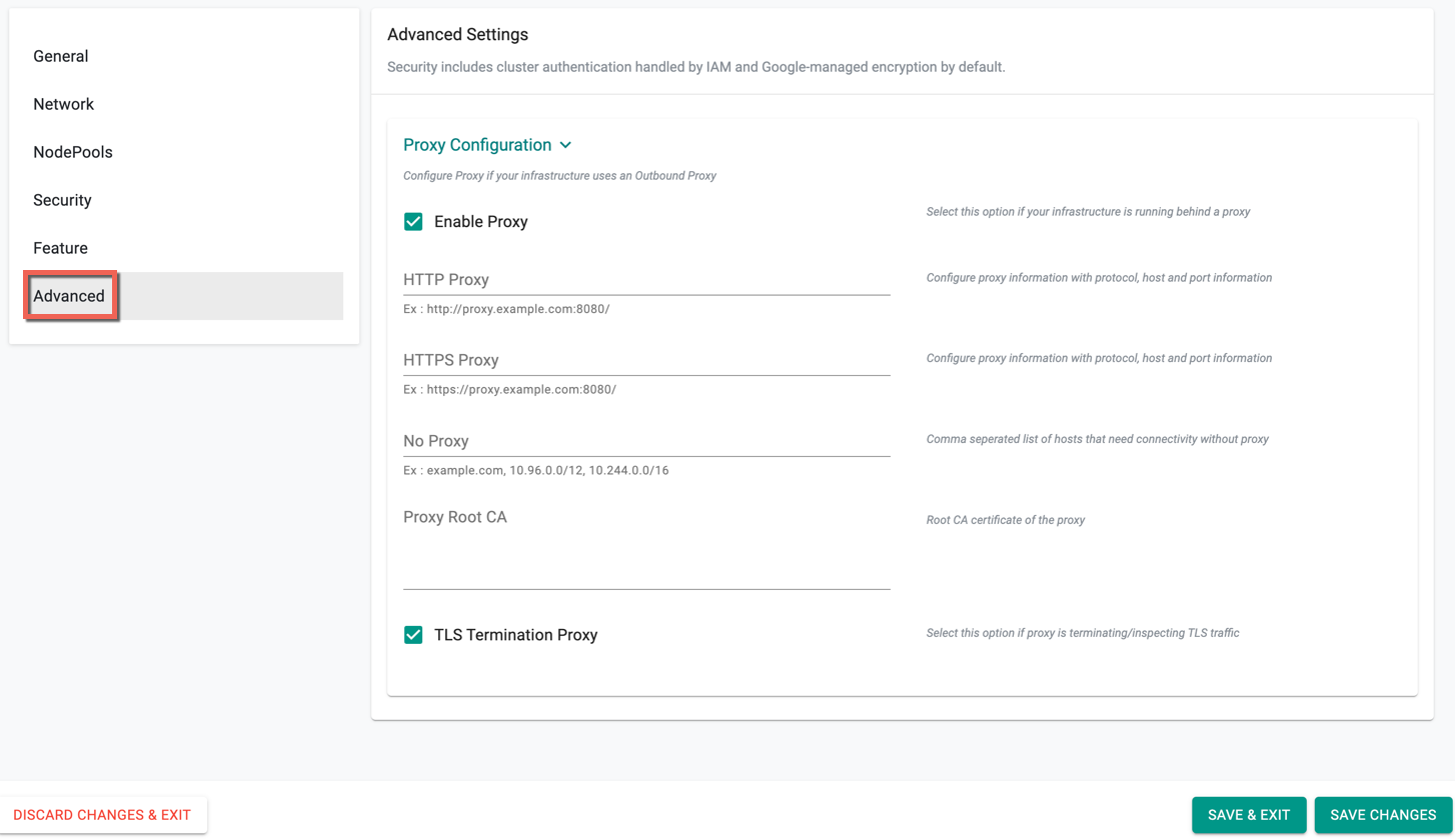
Advance Setting (Optional)
Proxy Configuration
Optionally, users can provide Proxy Configuration details.
- Select Enable Proxy if the cluster is behind a forward proxy.
- Configure the http proxy with the proxy information (ex: http://proxy.example.com:8080)
- Configure the https proxy with the proxy information (ex: http://proxy.example.com:8080)
- Configure No Proxy with Comma separated list of hosts that need connectivity without proxy. Provide the network segment range selected for provisioning clusters in the vCenter (ex: 10.108.10.0/24)
- Configure the Root CA certificate of the proxy if proxy is terminating non MTLS traffic
- Enable TLS Termination Proxy if proxy is terminating non MTLS traffic and it is not possible to provide the Root CA certificate of the proxy.
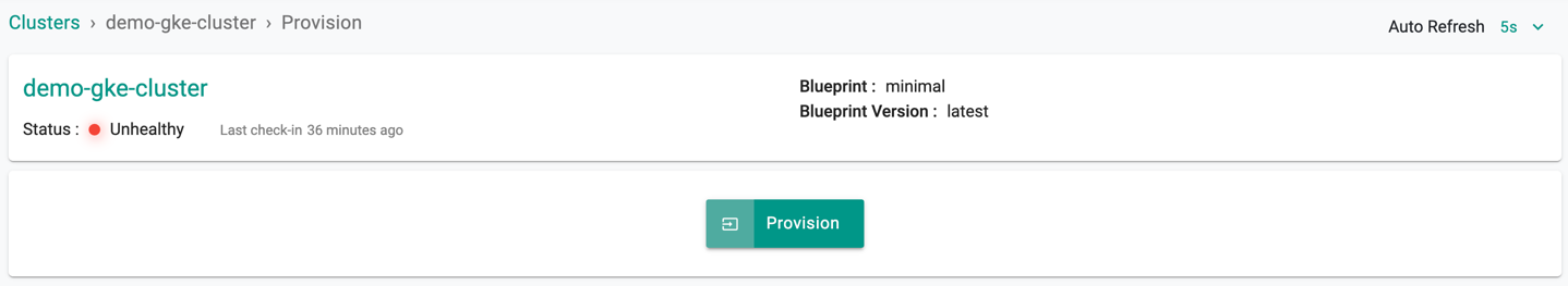
Once all the required config details are provided, perform the below steps
- Click Save Changes and proceed to cluster provisioning
- The cluster is ready for provision. Click Provision
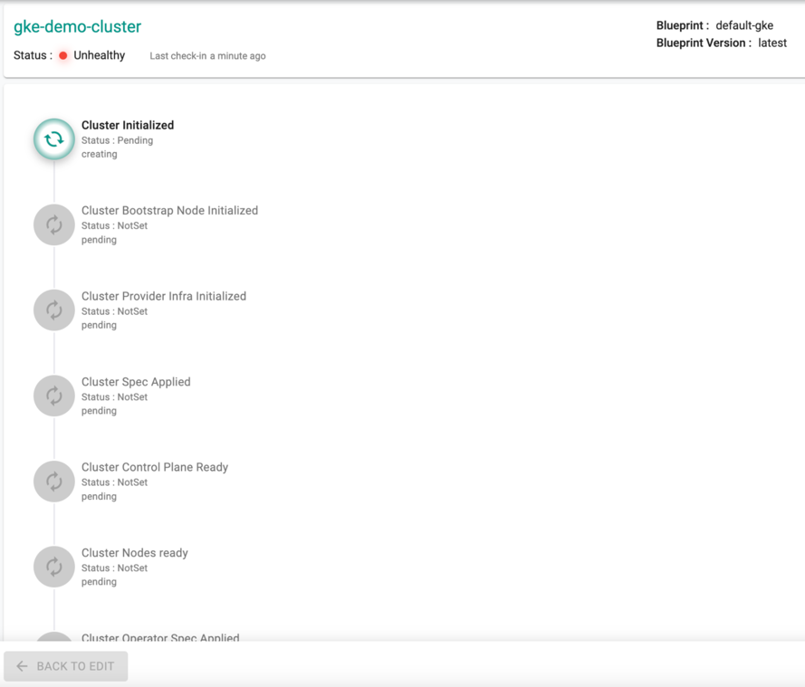
Provision Progress
Once the user clicks on Provision, the system begins to go through a list of conditions for a successful provisioning as shown below
Successful Provisioning
Once all the steps are complete, the cluster is successfully provisioned as per the specified configuration. Users can now view and manage the GKE Cluster in the specified Project in the Controller. On successfully provisioning, the user can view the dashboards
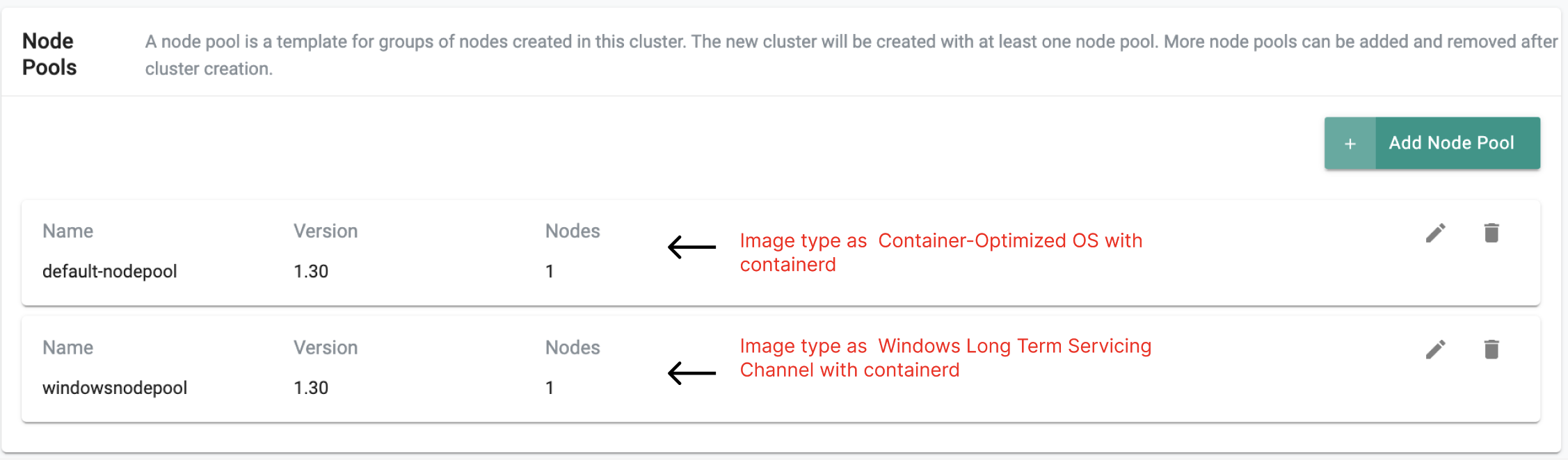
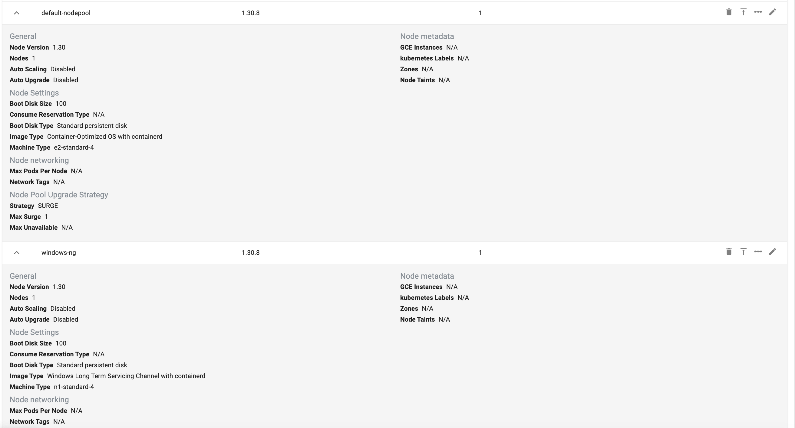
NodePools With Windows Nodes
To add Windows-based node pool in your cluster, ensure the following configuration for your cluster:
- A node pool with Container-Optimized OS with containerd (
cos_containerd) image type required for system components. These components are essential for the cluster’s operation and are not supported on Windows nodes. - A Windows-based node pool with Windows Long Term Servicing Channel (LTSC) and
containerd(windows_ltsc_containerd) image type.
CLI Node Pool Config Snippet
nodePools:
- machineConfig:
    bootDiskSize: 100
    bootDiskType: pd-standard
    imageType: COS_CONTAINERD
    machineType: e2-standard-4
    reservationAffinity: {}
    management: {}
    name: default-nodepool
    nodeVersion: "1.30"
    size: 1
    upgradeSettings:
    strategy: SURGE
    surgeSettings:
        maxSurge: 1
        maxUnavailable: 0
- machineConfig:
    bootDiskSize: 100
    bootDiskType: pd-standard
    imageType: WINDOWS_LTSC_CONTAINERD
    machineType: n1-standard-4
    reservationAffinity: {}
    management: {}
    name: windows-ng
    nodeVersion: "1.30"
    size: 1
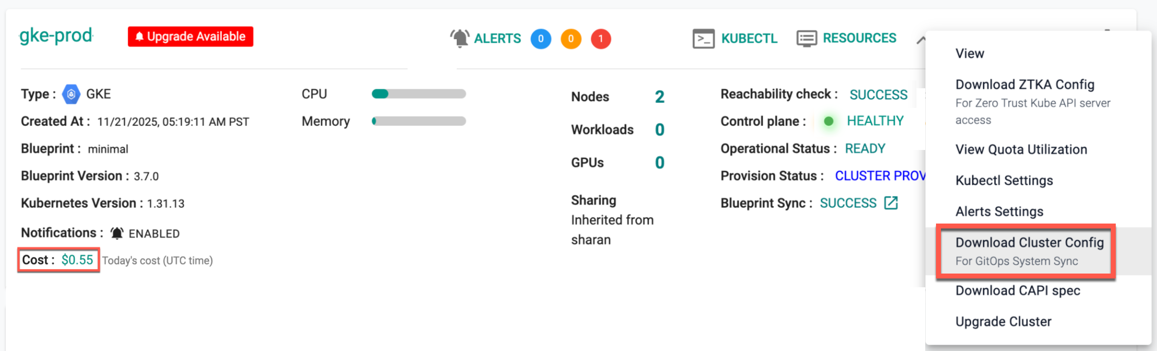
Download Config
Downloads the cluster configuration formatted for GitOps System Sync, either from the console, or using the RCTL CLI.
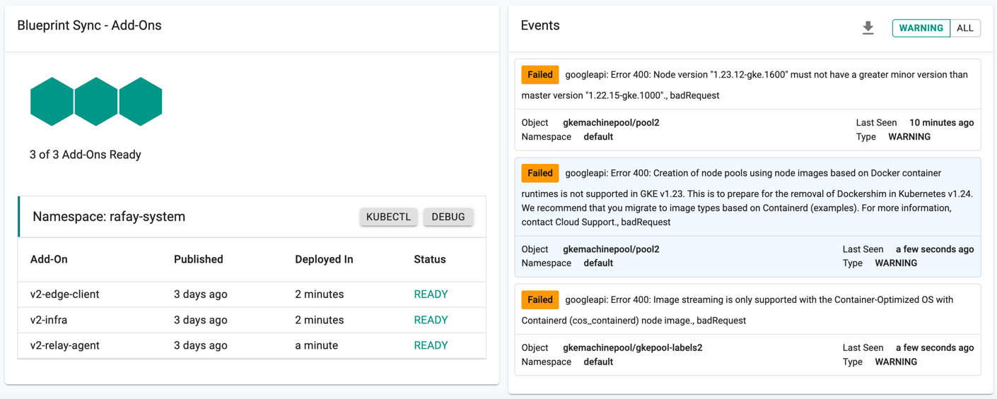
Failed Provisioning
Cluster provisioning can fail if the user had misconfigured the cluster configuration (e.g. wrong cloud credentials) or encountered soft limits in their GCP account for resources. When this occurs, the user is presented with an intuitive error message. Users are allowed to edit the configuration and retry provisioning
Refer to Troubleshooting section to learn about potential failure scenarios.
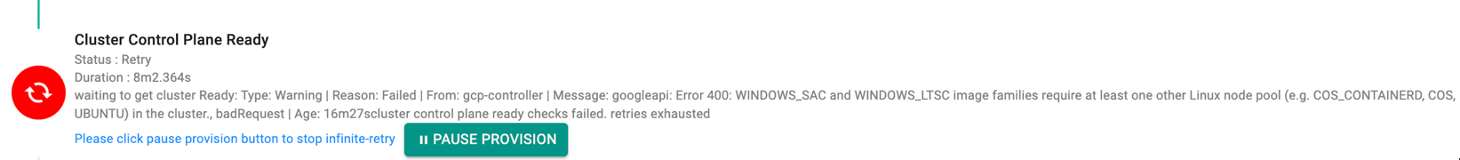
Pause/Resume Provisioning
During cluster provision, if an error occurs or provisioning fails due to any configuration issues, users can pause provisioning, rectify the issues and resume the cluster provisioning
- On receiving any error as shown below, click Pause Provision
- Once the configuration details are rectified, click Resume Provision as shown below
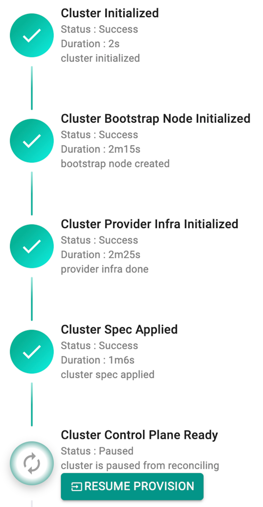
Note: This process cleans up the resources that are not required
Refer to Troubleshooting section to learn more about potential failure scenarios.